Vibe-Coding a PCB: Surprising Results from AI Design 🎉
I was expecting this to be pretty bad - but it actually came out quite nicely! Let’s dive into my latest adventure of vibe-coding a PCB. 🚀
The Inspiring Spark 🔥
After "vibe coding" a software-based vibing button in my last video, I decided to take things one step further: vibe-coding the actual hardware. The challenge? Let AI design a working ESP32-S3 development board from scratch.
Tools of the Trade 🛠️
For this experiment, I grabbed Atopile—a nifty tool that converts hardware project code into a KiCad PCB. And to assist me, I enlisted Claude, an AI coding assistant that really performed better than the usual suspects like Cursor for this task!
The AI Prompt 📜
Now, onto the fun part: the prompt. I needed the basics: an ESP32-S3 module, USB-C power and data lines, a 3.3V regulator, reset and boot buttons, status LEDs, a quick connector, and the usual passives.
Here’s the juicy bit of the prompt I tossed Claude's way:
I want to make an ESP32-S3 dev board.

We will need:
- ESP32-S3 module
- USB-C connector with 5.1K resistor on the CC lines
- 3.3V voltage regulator
- A red LED showing 5V is connected
- A green LED showing 3V3 is available
- A blue LED connected to a GPIO pin
- A QWIIC connector for peripherals
- Reset button
- Boot button
- Any additional passive components needed for the above
- An RC circuit for the enable pin on the ESP32-S3 module

The USB-C should provide 5V power and the data lines should directly connect to the ESP32-S3. GPIO19 and GPIO20 will handle USB D- and D+ respectively. All components must use LCSC part numbers and 0603 sizes.
The AI took this prompt and started generating components and wiring instructions. In the spirit of vibe coding, I didn’t peek at the code—just kept saying, “yes,” and watched what unfolded.
The AI Journey (aka, Chaos Ensues) 🌪️
At first, everything looked great! The build succeeded, all components were located and logged. But upon opening KiCad… nothing was wired up. 😱

With a quick nudge back to Claude, saying, “you forgot to connect anything,” we were back on track. After another build—success! Everything was wired, just as it should be.
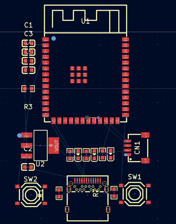
The Result 🎯
So, what did we cook up? Surprisingly functional:
- AMS1117 regulator
- Proper USB-C with CC resistors
- Differential USB routing
- Status LEDs
- Decoupling caps galore
- Reset and boot buttons
- A functional RC circuit on EN
While it’s not perfect (no schematic output unless you downgrade to KiCad 5), as a first pass from an AI? Not bad at all! 👏
Final Thoughts 💭
Vibe-coding a PCB feels like we're stepping into the future. We’re on the brink of describing hardware in natural language and letting AI do the nitty-gritty work. While it's not ready to replace a seasoned engineer, it’s definitely poised to be your enthusiastic (if slightly forgetful) assistant.
Next step? Should I send it off to PCBWay and see if it actually works? 🤔
Bill of Materials (BOM) 📝
Here's the BOM for those interested in diving into the components that were selected:
Designator,Footprint,Quantity,Value,Manufacturer,Partnumber,LCSC Part #
"C1, C2, C3",C0603,3,,Samsung Electro-Mechanics,CL10A106MQ8NNNC,C1691
"C4, C5, C6",C0603,3,,YAGEO,CC0603KRX7R9BB104,C14663
CN1,CONN-SMD_4P-P1.00_SM04B-SRSS-TB-LF-SN,1,,JST Sales America,SM04B-SRSS-TB(LF)(SN),C160404
LED1,LED0603-RD,1,,Hubei KENTO Elec,Blue light 0603,C2288
LED2,LED0603-RD,1,,Foshan NationStar Optoelectronics,NCD0603C1,C84264
LED3,LED0603-RD,1,,Hubei KENTO Elec,KT-0603R,C2286
"R1, R2",R0603,2,,UNI-ROYAL,0603WAF5101T5E,C23186
R3,R0603,1,,TyoHM,RMC060310KFN,C269701
"R4, R5, R6",R0603,3,,UNI-ROYAL,0603WAF3300T5E,C23138
"SW1, SW2",SW-SMD_4P-L5.1-W5.1-P3.70-LS6.5-TL_H1.5,2,,XKB Connectivity,TS-1187A-B-A-B,C318884
U1,WIRELM-SMD_ESP32-S3-WROOM-1,1,,Espressif Systems,ESP32-S3-WROOM-1-N16R8,C2913202
U2,SOT-223-3_L6.5-W3.4-P2.30-LS7.0-BR,1,,Advanced Monolithic Systems,AMS1117-3.3,C6186
USB1,TYPE-C-SMD_TYPE-C-24P-QCHT,1,,SHOU HAN,TYPE-C 24P QCHT,C456013